How To Change Dimension Settings In Autocad
You can change dimensions with the editing commands and with grip editing.
Grip editing is the quickest and easiest mode to change dimensions. How you edit dimensions depends on whether the dimension is associative.
Modify Associative Dimensions
Associative dimensions stay associated to dimensioned objects when these objects, and the associated geometry are selected and operated on with a single command. For example, if a dimension and its associated geometry are moved, copied, or arrayed in the same command, each dimension remains associated to its corresponding geometry.
In some circumstances, dimensions are automatically disassociated, including
- If the associated geometric object is erased
- If the associated geometric object undergoes a boolean operation such equally UNION or SUBTRACT
- If grip editing is used to stretch a dimension parallel to its dimension line
- If the clan to a geometric object is specified using the Credible Intersection object snap, and the geometric object is moved so that the apparent intersection no longer exists
In other circumstances, a dimension may go partially associated. If a linear dimension is associated with the endpoints of two geometric objects and one of the objects is erased, the remaining association is preserved. The disassociated finish of the linear dimension may and so exist associated with some other geometric object using DIMREASSOCIATE.
Note: The Command prompt displays a warning message when a dimension is disassociated.
Modify Non-associative Dimensions
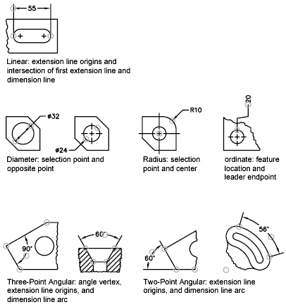
For non-associative dimensions, when you edit dimensioned objects, you must include the relevant dimension definition points in the pick set, or the dimension is non updated. Definition points determine the dimension location. For example, to stretch a dimension, y'all include the appropriate definition points in the selection set. You can easily include them past turning on grips and selecting the object so that the grips are highlighted.
The definition points for each type of dimension are indicated in the following illustrations. The heart point of the dimension text is a definition point for all dimension types.

If no angle vertex is shown, definition points are placed at the ends of the lines that form the bending. In the 2-line angular case, a definition signal is placed at the centre point of the dimensioned arc.
Annotation: Definition points are created on a special layer named DEFPOINTS that is never printed or plotted.
Use Dimension Line Grips
Hover over the grip on the endpoint of a dimension line to quickly access the following functionality:
- Stretch. Stretches the extension lines to move the dimension line further away or closer to the object being dimensioned. Use command line prompts to specify a different base of operations indicate or re-create the dimension line.
- Continue dimension. Invokes the DIMCONTINUE command.
- Baseline dimension. Invokes the DIMBASELINE command.
- Flip arrow. Flips the direction of the dimension arrowhead.
Modify Exploded Dimensions
You tin edit exploded dimensions equally you would any other objects because an exploded dimension is a drove of separate objects: Lines, second solids, and text. Occasionally yous may demand to explode a dimension to perform operations such as creating a break in a dimension line or extension line. Once a dimension is exploded, you lot cannot reassociate the dimension into a dimension object.
Source: https://knowledge.autodesk.com/support/autocad/learn-explore/caas/CloudHelp/cloudhelp/2019/ENU/AutoCAD-Core/files/GUID-BDD8C619-AB31-49D8-AE55-465EE6FAB61D-htm.html

0 Response to "How To Change Dimension Settings In Autocad"
Post a Comment